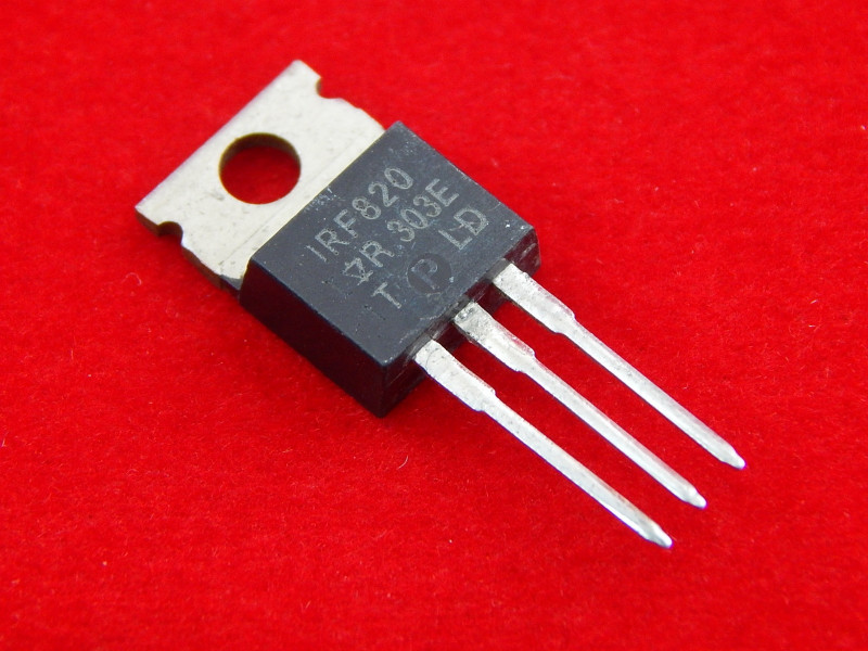
Irf820 Mosfet
| Номер произв | IRF820 | ||||
| Описание | N - CHANNEL 500V - 2.5ohm - 2.5 A - TO-220 PowerMESH] MOSFET | ||||
| Производители | STMicroelectronics | ||||
| логотип | |||||
1Page
N - CHANNEL 500V - 2.5 Ω - 2.5 A - TO-220 TYPE RDS(on) IRF820 <3Ω s TYPICAL RDS(on) = 2.5 Ω s 100% AVALANCHE TESTED s GATE CHARGE MINIMIZED This power MOSFET is designed using the OVERLAY™ process. This technology matches standard parts from various sources. s HIGH CURRENT, HIGH SPEED SWITCHING s DC-AC CONVERTERS FOR WELDING POWER SUPPLIES AND MOTOR DRIVER 2 TO-220 ABSOLUTE MAXIMUM RATINGS Parameter VDS Drain-source Voltage (VGS = 0) VDGR ID Drain- gate Voltage (RGS = 20 kΩ) Drain Current (continuous) at Tc = 25 oC 500 2.5 IDM ( •) Drain Current (pulsed) 10 Derating Factor dv/dt(1) Peak Diode Recovery voltage slope Tstg Storage Temperature Tj Max. Operating Junction Temperature (•) Pulse width limited by safe operating area (1) ISD ≤2.5 A, di/dt ≤ 50 A/µs, VDD ≤ V(BR)DSS, Tj ≤ TJMAX First Digit of the Datecode Being Z or K Identifies Silicon Characterized in this Datasheet V V A W V/ ns oC 1/8
THERMAL DATA Rth j -a m b Tl Max Max Typ 1.56 0.5 oC/W oC/W AVALANCHE CHARACTERISTICS IAR Parameter (pulse width limited by Tj max) (starting Tj = 25 oC, ID = IAR , VDD = 50 V) 2.5 Unit mJ ELECTRICAL CHARACTERISTICS (Tcase = 25 oC unless otherwise specified) S ymb ol IDSS P a ra m et er Dr ain- sou rc e ID = 250 µA VGS = 0 VDS = Max Rating Tc = 125 oC Current (VDS = 0) Min. Typ. Max. 50 Unit µA nA S ymb ol RDS( o n ) P a ra m et er Gate Threshold VDS = VGS ID = 250 µA Resistance On St ate Drain Current VDS > ID(on) x RDS(on) max Min. Typ . Max. Unit 2.5 3 2.5 A S ymb ol Ciss Crss Forward Input Capacitance Reverse Transfer Test Conditions Min. Typ . Max. S 360 pF 6 pF
ELECTRICAL CHARACTERISTICS (continued) S ymb ol tr Turn-on Time Qg Total Gate Charge Qgd Gate-Drain Charge VDD = 250 V ID = 2.1 A VGS = 10 V VDD = 400 V ID = 2.1 A VGS = 10 V Typ . 8 5 Max. Unit ns nC SWITCHING OFF tr(Vo f f) tc Off-voltage Rise Time Cross-over Time VDD = 400 V ID = 3.8 A (see test circuit, figure 5) Typ . 5 Max. ns ns S ymb ol Test Conditions ISDM (•) Source-drain Current VSD (∗) Forward On Voltage trr Reverse Recovery Qrr Reverse Recovery VDD = 100 V Tj = 150 oC Charge Current (∗) Pulsed: Pulse duration = 300 µs, duty cycle 1.5 % Min. Max. 15 A 1.6 V 980 µC Safe Operating Area 3/8 | |||||
| Всего страниц | 8 Pages | ||||
| Скачать PDF | [ IRF820.PDF Даташит ] | ||||


N-mosfet Irf 820


Soundmax integrated digital high definition audio driver download for windows. IRF820 datasheet, IRF820 pdf, IRF820 data sheet, datasheet, data sheet, pdf.

Irf820 Mosfet
- IRF820 MosFET Mos FET Transistor NPN 50W 500V 2.5A.
- IRF820, IRF820 Datasheet, IRF820 PDF, Power MOSFET.
- IRF820 Datasheet(HTML) 1 Page - STMicroelectronics: zoom in zoom out 1 / 8 page. N - CHANNEL 500V - 2.5. This power MOSFET is designed using the. Company’s consolidated strip layout-based MESH. OVERLAY ™ process. This technology matches. And improves the performances compared with. Standard parts from various sources.
